Lingua

Ottieni una citazione
Ottieni una citazione
 Casa / Notizia / Notizie del settore / How Do UN Butt Welding Machines Compare Across Hand, Pneumatic and Flash Welding?
 2026.08.25
 Notizie del settore
Joining two metal bar ends face to face without filler material is one of the oldest challenges in metal fabrication, and resistance butt welding remains one of the most reliable answers to it. Current passes through the contact interface, heat builds at the joint, and axial pressure forges the two ends into a single continuous piece. Within this family of processes, a flash weld stands out because the workpieces are brought together with a controlled gap, allowing arcing and rapid melting at the interface before the final forging stroke.
Wire drawing lines, rebar mills, tube plants, and rail yards all depend on some version of this joining method, because the alternative approaches, such as arc welding with filler rod, are too slow or too inconsistent for continuous production runs. The choice of equipment tier, from a simple hand operated clamp to a fully automated flash unit, depends heavily on batch size, cross-section, and how much operator judgment a shop wants to remove from the process.
The remainder of this guide walks through the three common tiers of butt welding equipment, explains how the flash welding cycle actually unfolds, and compares real operational data across cycle time, throughput, and industry usage so that a fabrication team can match equipment capability to production goals.
The UN Butt Welding Machine line is organized around a simple idea: as production volume and cross-section size increase, the amount of manual judgment involved in clamping, heating, and upsetting should decrease. That progression produces three distinct machine tiers, each aimed at a different point on the production curve.
| Tier | Operating Principle | Best Suited For |
|---|---|---|
| Hand Operated | Manual clamping and manual upset stroke | Small batches, workshops, field repair |
| Pneumatic | Air cylinder controlled clamping and upset force | Medium batches, mixed cross-sections |
| Flash Butt Welding | Automated flashing cycle with programmed upset | Continuous, high-volume production |
Each tier uses the same underlying resistance butt welding principle, but the amount of automation changes how repeatable the joint quality is from piece to piece. The sections below look at each machine type individually before moving into a direct performance comparison.
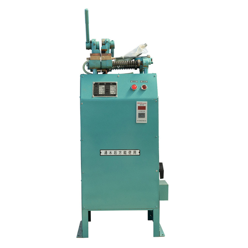
The UN1 Hand Operated Butt Welding Machine relies on a manual lever to bring the two workpiece ends together and apply upset pressure once the interface has reached welding temperature. Because the operator directly feels the resistance through the lever, experienced technicians can adjust stroke speed on the fly, which makes this tier well suited to mixed material runs where cross-sections change frequently.
This machine type is common in small metalworking shops, tool rooms, and field repair units where a compact footprint and low capital cost matter more than raw throughput. The trade-off is repeatability: joint quality depends on operator skill, so batch-to-batch consistency is generally lower than with pneumatic or flash equipment.
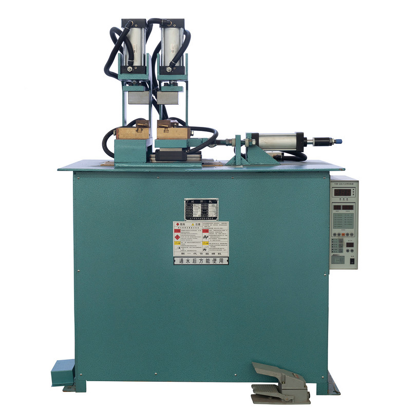
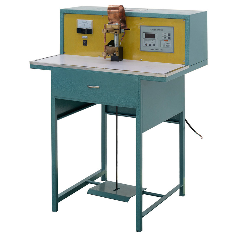
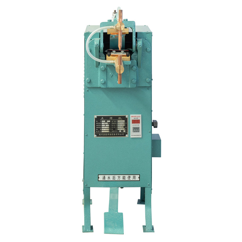
The UN2 pneumatic butt welding machine replaces the manual lever with an air cylinder, so clamping force and upset stroke are delivered at a consistent, pre-set pressure rather than depending on how hard an operator pushes. This single change noticeably improves repeatability compared with hand operated equipment, while still keeping the machine simpler and less expensive than a fully automated flash welding unit.
Because the pneumatic system can be tuned for different bar diameters, this tier tends to serve as the workhorse for medium-volume production lines producing fasteners, wire products, and small structural components. Cycle times drop meaningfully compared with manual operation, and the reduced physical effort also lowers operator fatigue on longer shifts.
| Factor | Typical Behavior |
|---|---|
| Clamping Force | Set and repeated via air pressure regulation |
| Operator Involvement | Loading, unloading, and cycle initiation |
| Ideal Batch Size | Medium, recurring production runs |
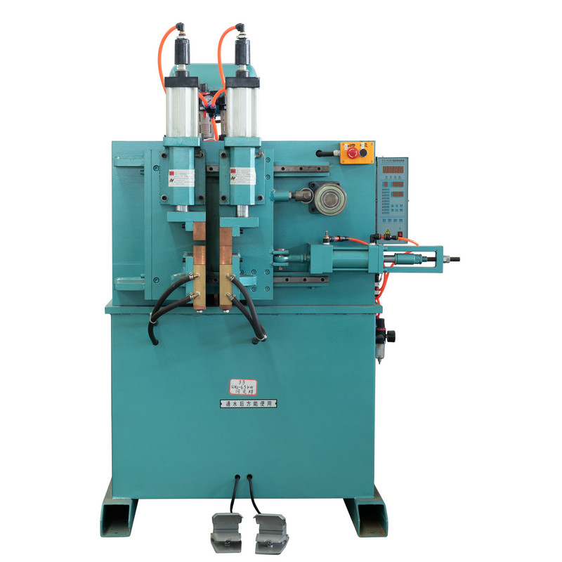
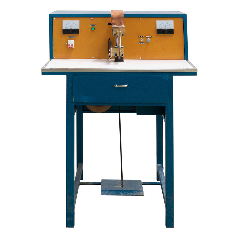
The UN3 Flash Butt Welding Machine automates the entire sequence: approach speed, flashing duration, and the final upset stroke are all controlled by programmed parameters rather than operator judgment. This is the equipment tier most closely associated with the term flash weld in industrial settings, because the controlled arcing and melting phase is what defines flash welding as distinct from simple resistance butt welding.
Rail sections, large diameter pipe, and continuous wire rod lines rely on this tier because it can hold tight, repeatable parameters across thousands of consecutive welds. The higher capital cost is offset by dramatically reduced cycle time and lower dependence on individual operator skill, which matters most when a single weak joint can shut down an entire production run.
Flash welding is often described in general terms, but the process follows a specific, repeatable sequence once the machine is programmed. Understanding each stage helps explain why an electric butt welding machine at this tier produces such consistent joints compared with manual approaches.
During flashing, the two ends are brought close enough that small contact points arc and burn away rapidly, generating localized heat exactly at the interface rather than spreading it through the bulk material. Once the programmed flashing time or displacement is reached, the upset stroke drives the ends together under high force, expelling molten and oxidized material outward as flash, which is later trimmed and machined flush.
Choosing between hand operated, pneumatic, and flash butt welding equipment usually comes down to five practical factors: how automated the cycle is, how fast each weld completes, how much capital the machine requires, how simple it is to maintain, and how consistent the resulting joint is from part to part.
The pattern is consistent with what fabricators typically report in the field: hand operated equipment scores well on capital cost efficiency and maintenance simplicity because there is little to break, but it trails on automation and cycle speed. Flash butt welding equipment inverts that pattern, trading a larger upfront investment for automation, speed, and joint consistency.
Beyond qualitative comparison, cycle time and shift output are usually the deciding numbers for a production manager evaluating butt welding equipment. The two charts below use representative operating figures for a mid-size bar cross-section.
Over a full shift, the gap widens considerably. An automated flash butt welder can finish a shift with roughly four to five times the output of hand operated equipment on the same bar size, which is why continuous casting, rail, and wire rod plants standardize on the flash tier even though the initial equipment cost is higher.
Different industries lean on different tiers of this equipment depending on cross-section size, tolerance requirements, and run length. The chart below reflects a general distribution of where flash welding and resistance butt welding equipment see the heaviest use.
Rail leads because flash welded joints hold up well under repeated cyclic loading, and pipeline work follows closely for the same reason. Wire and cable producers, along with automotive component makers, tend to split between pneumatic and flash tiers depending on wire gauge, while structural steel fabrication still makes meaningful use of hand operated and pneumatic equipment for lower-volume custom work.
Matching equipment to production reality avoids two common mistakes: over-investing in automation that a low-volume shop cannot fully use, or under-investing in a machine that becomes a bottleneck once demand grows. A few practical questions help narrow the decision.
Many shops that scale from prototype or repair work into recurring production actually move through all three tiers over time, starting with a hand operated unit and eventually adding pneumatic or flash capacity as order volume justifies the investment.
Regardless of tier, a few maintenance habits meaningfully extend equipment life and keep joint quality consistent. Electrode and clamp jaw condition matters most, since worn contact surfaces introduce resistance variation that shows up directly in weld quality.
| Maintenance Task | Recommended Frequency | Why It Matters |
|---|---|---|
| Clamp jaw inspection | Daily to weekly | Worn jaws cause inconsistent current flow |
| Cooling system check | Weekly | Overheating shortens electrode life |
| Pneumatic seal inspection | Monthly | Air leaks reduce clamping consistency |
| Control calibration | Quarterly | Keeps flashing and upset parameters accurate |
Operators running an electric butt welding machine should also log cycle parameters over time, since gradual drift in flashing duration or upset force is often the earliest warning sign of a component that needs servicing before it causes a defective joint.
Resistance butt welding simply presses two heated ends together, while a flash weld introduces a controlled arcing and melting phase before the final forging stroke, which typically produces a narrower heat affected zone and cleaner joint.
Yes, for low-volume, mixed cross-section, or field repair work, a hand operated machine remains cost effective because it avoids the capital and setup time associated with automated equipment.
Based on typical cycle data, flash butt welding equipment can complete a weld in roughly one third the time of a pneumatic machine on a comparable cross-section, which compounds significantly over a full production shift.
Consistency mainly depends on how tightly the machine holds flashing time, displacement, and upset force across repeated cycles, which is why automated control systems outperform manual adjustment in high-volume settings.
The core tasks such as clamp jaw and cooling system checks apply to all tiers, but pneumatic and flash equipment add air system and control calibration checks that hand operated machines do not require.
Rail, pipeline, wire and cable, and automotive component production make up the largest share of flash welding use, primarily because these applications involve continuous runs and cyclic load requirements that favor consistent, automated joints.
Prodotti consigliati

Prodotto
Informazioni di contatto.
+86-152-5712-5882
Fax: +86-563-2269966
N. 21 GUANGPING ROAD, GUANGDE Economic Development Zone, città di Guangde, provincia di Anhui
Codice QR